|
|
Kit Building Guide | |
| Ham Radio India | ||
|
| ||
| Home | Forum | Radio Astronomy | Shopping Mall |
| ||||||||||||||||||||||||||||||||||||||||||||||||||||
|
Resources | ||||||||||||||||||||||||||||||||||||||||||||||||||||
| Amateur Radio | |
| Radio Astronomy | |
| Ayurveda | |
| Yoga | |
| Gita | |
| Web Directory | |
| Amateur Software | |
| News Channels | |
| Shopping Mall | |
| Free Classifieds | |
| Photo Gallery | |
|
How to? - Kit Building | ||||||||||||||||
|
| |||||||||||||||
|
IDENTIFYING KIT PARTS & COMPONENTS | ||||||||||||||||
|
RESISTORS:
The universal color coding of resistors does not change, fortunately, but resistor body colors and the style of wire leads can vary. Also, resistors may be packed loose or supplied on tape strips. Install any resistor as shown on the PC board parts layout diagram. Keep all leads as short as possible.
CERAMIC DISC CAPACITORS:
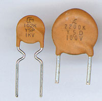
It is helpful practice to become as familiar as possible with the various marking codes for ceramic capacitors. The first fact to keep in mind is that there are several accepted methods for marking the value of these capacitors! While resistor color codes have withstood changing times over many decades, the protocols for marking evermore-tiny capacitors have many variations! While capacitors also can be color-coded, some Kits use disc capacitors marked by a number-letter code. The first two digits establish the first two numbers of the value. The third digit is the multiplier. The letter designates the manufacturing 'tolerance" or accuracy for the value printed. Values under 100 picofarads, used widely in FM and VHF kits, are printed clearly with no need to interpret them further. Small capacitors stamped 4.7, 10, 15, 33, 68 and so forth are 4.7, 10, 15, 33, 68 picofarads respectively! A 100 picofarad capacitor, also commonly used in kits, can be marked either 100 or 101! If it's marked 100, believe it. If it is marked 101, the value is 10 (first 2 digits) X 10 (3rd digit multiplier) = 100 picofarads! If it is marked 101J, we know that it is made to 5% accuracy, while H signifies 3% and K is 10%. Rule of thumb: If the 3rd digit is a 0, you may assume the value is in picofarads, and you can take the three numbers together as the pico-farad value for that capacitor. So, just as in the above example, both "470" and "471" are 470 pf. There is a growing trend to mark capacitors very clearly in nanofarads. Be sure not to confuse 10nf or 100nf with 10 or 100 picofarads! There's more! Some manufacturers don't care about codes and print the value and tolerance VERY plainly. E.g.,. "820+20%" means 820 pf. at 20% tolerance. Yet another style of capacitor for values such as .1 uf is manufactured as a neat, rectangular block, with the value and other identifying data stamped on the top. For example, the information of interest to you in the marking ".1J63" on such a capacitor is the ".1" for .1 uf.
ELECTROLYTIC CAPACITORS:
Virtually every kit uses one or more electrolytic capacitors. These are polarized capacitors, which means that they have positive (+) and negative (-) leads and MUST be installed correctly on the PC board. Your kit instruction manual is likely to be very clear about correct polarity of these capacitors, and the positive (+) side is generally etched on the PC-board itself. Ordinarily, only the negative side is marked on the capacitor.
INDUCTORS:
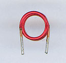
Coils or inductors supplied with kits can come to you in ANY of these styles:
Your kit manual provides clear information for correctly identifying any coils used in it.
DIODES:
If a kit uses one diode, or a number of the same kind of diode, you are in luck. Just be sure to understand the difference between the cathode (banded) end and the anode before installing. If the kit uses several different diodes, it is necessary to identify each of them correctly. Believe it or not, there ARE printed markings on even tiny diodes. You'll need a magnifying glass even if you claim perfect 20-20 eyes! If you are unsure about correct diode identification, please ask for help. An LED (light-emitting diode) is indeed a diode, not a lamp. If your kit uses LED's, the instruction manual shows you clearly how to install them correctly. A numeric display such as used in frequency counters or tone decoders is a series of LED's.
TRANSISTORS:
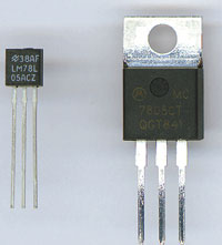
The most common single transistor for most kits is the versatile NPN 2N3904. We use a variety of other types as well. Please pay close attention to how the "flat" or other special characteristic of any transistor is oriented on your kit manual's PC-board drawing.
INTEGRATED CIRCUITS ("IC's"):
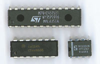
Many kits employ at least one IC. And, for most kits, we encourage careful, direct soldering of the IC to the PC board. Years of experience shows us that IC sockets themselves can cause needless problems. If you prefer to use sockets, buy them and do so. Be very careful in setting IC's into sockets. It is VERY important to orient the end with the notch, ball or band in the direction shown on the PC-board drawing!
NON-CRITICAL PART VALUES: The majority of components in any circuits have a specific value for a specific purpose. For example, a certain resistor is needed to provide correct bias to a transistor. And, of course, the frequency of tuned circuits is directly determined by the capacitor and inductor. However, some parts values are not critical at all, and your kit manual may specify, for example, that an electrolytic capacitor may be in a range of 2 to 5 uf or 4.7 to 10 uf. Or we can state a range of values for resistors or potentiometers or that "any" NPN transistor will work in a given circuit position.
| ||||||||||||||||
|
| |
|
| |
|
| |
|
|


