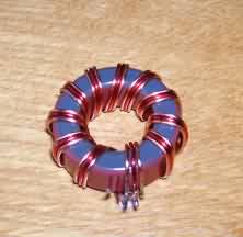
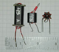
Hopefully,
if you're
reading
this, you
are
working on
kit
building
or trying
to
understand
handling
of totoids.
I find kit
building
to be one
of the
most
enjoyable
experiences
in Amateur
Radio.
There
might be
saveral
tasks in
entire kit
building.
One of
these
tasks is
winding
toroids.
If you are
into kit
building
you will
need to
face this
task at
some point
since
toroids
are used
in many
circuits
such as
oscillators,
filters
and are
also used
as
transformers.
This
guide will
give you
some tips
to help
the
process go
smoothly
and may
actually
make it a
bit more
enjoyable.
SUGGESTED
TOOLS:
You may
need some
tools to
perform
this task.
They
include:
Magnifying
Glass or
Magnifying
Visor
(preferred)
Butane
Lighter
Small
Jewelers
Screwdriver
Fine point
black
Magic
Marker
(sharpie)
Fine
Sandpaper
Soldering
Iron
Solder
Solder Pot
(optional)
or heavy
soldering
Iron
(250W)
Long nose
pliers
Ohmmeter
WINDING
THE TOROID:
The first
step is to
follow the kit
manufacturer's
instructions
very
carefully.
The
instructions
will
specify
which core
(ferrite
or iron
powder),
the length
of wire to
use, and
how many
turns are
required.
Many of
the cores
that you
will use
are color
coded.
If not you
may find
the cores
bagged
separately
to
minimize
the
possibility
of using
the wrong
one.
You
must make
sure you
select and
use the
proper
core and
wire.
Some
toroids
may
specify a
smaller
gauge wire
when many
turns must
be wound
on the
core.
The
instructions
will
indicate
how many
turns are
required
for the
toroid and
how to
wind it
(start
point and
which
direction
to wind
in).
The method
of winding
is very
important
for two
reasons.
First,
if the
toroid is
not wound
as
designated,
it may not
fit on the
board as
intended.
Second,
some
windings
on the
toroid may
need to
maintain a
particular
polarity.
These
toroids
are said
to be
wound with
a certain
"sense"
(reference
of one
winding to
another)
that must
be
maintained
for the
circuit to
perform
properly.
After
winding a
toroid
use a
magnifying
glass and
a small
jewelers
screwdriver
to check
the number
of turns.
First
separate
the turns
as much as
possible
on the
core.
Then view
the toroid
under a
magnifying
glass or
magnifying
visor and
use the
small
jewelers
screwdriver
as a
pointer to
help count
the number
of turns.
Always
count
twice.
EACH TIME
THE WIRE
PASSES
THROUGH
THE CENTER
OF THE
TOROID, IT
COUNTS AS
ONE TURN.
Some
toroids
will
require a
seconding
winding.
You must
follow the
instructions
carefully
to make
sure that
it is
wound with
the
correct
"sense".
There are
also some
toroids
(bi-filar
and tri-filar)
that
require
that two
or three
pieces of
magnet
wire be
twisted
together
before
winding
them on
the toroid.
Kit
manufacturers
are
usually
very good
at
explaining
how the
toroids
should be
wound and
how they
should
look when
complete.
PREPARING
THE LEADS:
click to enlarge
Now that
you have
wound the
toroid it
is time to
prepare
the leads.
First you
must
determine
how the
toroid is
to be
mounted on
the board
(laying
flat or
standing
vertical).
You will
then need
to mark
the wire
leads
using the
fine tip
black
Magic
Marker
(Sharpie).
Mark the
leads at
the edge
of the
toroid
just
before the
lead would
hit the pc
board when
the toroid
is mounted
flush.
Mark it
this close
to the
toroid
because
you will
need to
unwind one
turn from
each lead
in order
to remove
the
enamel.
When
you rewind
each turn,
the leads
will
usually be
slightly
longer due
to the
windings
being a
bit
tighter on
the toroid.
This is
caused by
the enamel
removal
and
rewinding
process.
For this
technique,
the mark
on the
wire will
wind up
being at
the
perfect
location
for
removing
the enamel
so that
you end up
with a
good
solder
connection
and
minimum
lead
length.
REMOVING
THE
ENAMEL:
Now we
will see
ways to
remove the
enamel
from each
lead.
First,
unwind one
turn from
each end
of the
toroid.
If this is
a bi-filar
or tri-filar
toroid you
will need
to untwist
the leads
and work
with one
at a time.
Also make
sure that
you have
enough
clearance
between
the
untwisted
leads so
that
heating
one won't
cause a
short with
any of the
other
leads.
Now
while
holding
the toroid
by the
core,
place the
end of one
of the
leads over
the flame
from the
butane
lighter.
You will
find that
the enamel
burns at a
very
predictable
rate.
When you
remove the
wire from
the flame,
a bit more
of the
enamel
will burn.
With some
practice
you will
be able to
burn off
the enamel
to the
precise
point that
you marked
the wire
with the
black
Magic
Marker
(Sharpie).
Until you
become
proficient
at this, I
suggest
using
slightly
longer
pieces of
wire when
winding
the
toroids.
The leads
should be
1 - 2
inches
long after
winding
all of the
turns on
the toroid.
This will
give you a
more
comfortable
amount of
wire to
work with
when
burning
off the
enamel.
Once
you have
burned the
enamel you
can remove
the ash by
using the
fine
sandpaper.
Take a
small
piece
approximately
1/2 X 2
inches and
fold it in
half
lengthwise.
Place the
wire
between
the folded
pieces of
the
sandpaper
and apply
a small
amount of
pressure.
Then
gently
draw the
wire away
from the
sandpaper.
Do this
several
times
slightly
rotating
the wire
after each
time.
This
should
remove all
of the ash
and leave
a shinny
wire.
Do not
apply too
much
pressure
since this
may cause
the wire
to break.
Now using
the
soldering
iron and
solder,
tin the
bare
leads.
Usually
any enamel
that was
not
removed by
the
sandpaper
will come
off in the
tinning
process.
When you
have
completed
all of the
leads
rewind the
one turn
for each
lead that
you
removed.
If the
toroid was
a bi-filar
or tri-filar,
don't
forget to
re-twist
the leads
before
winding
the one
turn back
on the
toroid.
After
re-twisting
the wires,
make sure
that the
bare
tinned
leads are
not
shorted.
Next you
must count
the turns
of wire on
the toroid
to confirm
that you
have the
correct
number.
Just a
quick word
about
those
windings
that are
only 1 - 4
turns.
You will
need to
handle
these a
little
differently.
Wind the
toroid as
described
previously
and mark
the leads
for
removal of
the
enamel.
Remove all
of the
windings
from the
toroid.
This is
necessary
since
attempting
to sand
the wire
with the
windings
still
installed
on the
toroid
will cause
you to
pull the
wire right
off the
core.
There just
aren't
enough
turns to
hold it in
place.
Hold the
wire with
the long
nose
pliers
when
burning
off the
enamel and
removing
the ash
with the
fine
sandpaper.
If you
hold the
wire at
the very
end while
removing
the
enamel,
the spot
where you
held it
will wind
up being
cut off
after the
soldering
process.
That way
you won't
have to
worry
about any
damage to
the wire
where it
was held
by the
long nose
pliers.
Once the
enamel has
been
removed
you can
rewind the
toroid and
tin the
leads as
described
previously.
ALTERNATE
METHOD OF
REMOVING
THE
ENAMEL:
There is
an
alternate
method of
removing
the enamel
that is
favored by
many. This
method
uses a
solder pot
or
soldering
iron to
remove the
enamel and
tin the
wire in
one step.
If you
have a
solder
pot, turn
it on and
wait until
it comes
up to
temperature.
When it is
at the
proper
temperature,
the solder
will be in
a molten
state.
To remove
the
enamel,
insert the
wire into
the molten
solder up
to the
mark you
made to
indicate
how much
enamel
needed to
be
removed.
The enamel
will melt
off
and the
solder
will tin
the wire
in one
step.
The ash
from the
enamel
will
remain in
the solder
in the
pot.
A
soldering
iron can
also be
used to
remove the
enamel.
The method
works best
with a
temperature
controlled
iron or
workstation.
If you can
adjust the
temperature
on your
iron, you
will want
to set it
between 750
and 800 degrees
F.
If
your iron
has
removable
tips, put
on a
larger tip
then you
would
normally
use for pc
board
soldering.
The larger
tip will
hold more
solder and
will
maintain a
more
constant
temperature
during the
enamel
removal
process.
To start
removing
the
enamel,
melt a
large blob
of solder
on to the
tip.
The solder
should
melt
almost
instantly
and should
remain
molten on
the
soldering
iron tip.
Next, run
the wire
slowly
through
the solder
on the tip
until you
reach the
mark you
had put on
the wire. You
will see
the enamel
being
removed
and the
wire being
tinned at
the same
time.
The solder
will
retain the
ash from
the
enamel.
This will
require
you to
clean the
contaminated
solder off
of the
soldering
iron tip
and melt
fresh
solder on
to the tip
frequently.
SPACING
THE LEADS
AROUND THE
TOROID:
At this
point you
will want
to make
sure the
windings
are spaced
as evenly
as
possible
on the
core.
In most
cases the
windings
should
cover
about 85%
of the
core.
The
instructions
will
usually
tell you
how the
finished
toroid
should
look.
The
spacing of
the
windings
does
affect the
inductance
of the
toroid.
If you
have a
meter that
measures
inductance,
check the
inductance
of the
toroid and
compare it
to
the value
listed on
the
circuit
schematic
or table
of parts.
If you
need to
adjust the
inductance,
try
spreading
the turns
to
increase
the
inductance
or
compressing
the turns
to
decrease
the
inductance.
The
spacing of
the
windings
can also
be
adjusted
for best
performance
during the
final
circuit
alignment.
There will
usually be
references
in the
alignment
instructions
on how to
do this.
MOUNTING
AND
SOLDERING:
The next
step is to
mount the
toroid by
pulling
the leads
through
the proper
holes in
the board.
YOU MUST
BE VERY
CAREFUL,
ESPECIALLY
WHEN THE
TOROID HAS
MULTIPLE
LEADS.
It is very
easy to
put the
leads in
the wrong
holes.
Pull the
leads so
that the
toroid is
snug
against
the board.
Bend all
of the
leads to
hold the
toroid in
place.
Now solder
one lead.
When
soldering
the leads
pay
careful
attention
to how the
solder
flows.
One
of the
biggest
causes of
problems
with
toroids is
not
getting a
good
solder
connection
between
the toroid
leads and
the solder
pads.
The solder
joint
should
look
shinny,
smooth and
rounded
without
any voids.
If the
lead
appears to
be an
"island"
in a small
pool of
solder,
chances
are that
it is not
making
good
contact.
Now check
to make
sure the
toroid is
still snug
against
the board.
If not,
reheat the
solder
joint you
just made
while
applying
gentle
pressure
to the
toroid so
that it
will be
snug
against
the board.
When you
are
satisfied
with the
position
of the
toroid,
solder the
remaining
leads.
After
completing
the
soldering
it is
always
best to
double
check the
solder
joints
using an
ohmmeter.
Place the
leads from
the
ohmmeter
on the
solder
pads (not
the bare
leads) of
two of the
leads from
the same
winding of
the toroid
or that
are
electrically
connected
in the
circuit.
You should
measure
almost no
resistance.
If
the
resistance
is high or
infinite,
re-check
the solder
joints.
If you
still have
a problem,
you may
want to
try
repositioning
the wire
by heating
the solder
joint and
pulling a
small
amount of
it from
the toroid
side of
the board.
Check the
solder
joint and
add
additional
solder if
necessary.
Once you
are sure
that you
have good
solder
joints you
can cut
off the
excess
lead above
the solder
joints.
CALCULATING
REQUIRED
WIRE
LENGTH FOR
TOROIDS:
If you are
unsure of
how long
the wire
should be
for the
number of
turns
specified
on a
certain
size core,
you can
use the
table
below to
figure the
length.
CALCULATING
WIRE
LENGTHS
FOR
WINDING
TOROIDS
CORE
TYPE
|
IPT
|
T-12 |
0.163 |
T-16 |
0.202 |
T-20 |
0.252 |
T-25 |
0.327 |
T-30 |
0.412 |
T-37 |
0.426 |
T-44 |
0.529 |
T-50 |
0.577 |
T-68 |
0.700 |
T-80 |
0.800 |
T-94 |
1.006 |
T-106 |
1.364 |
T-130 |
1.394 |
T-157 |
1.760 |
T-184 |
2.300 |
T-200 |
1.850 |
T-225 |
1.950 |
T-225A |
2.850 |
T-300 |
2.080 |
T-300A |
3.080 |
|
|
CORE
TYPE
|
IPT
|
T-400 |
3.050 |
T-400A |
4.350 |
T-520 |
3.720 |
FT-23 |
0.230 |
FT-37 |
0.438 |
FT-50 |
0.595 |
FT-50A |
0.688 |
FT-50B |
1.188 |
FT-82 |
0.809 |
FT-87 |
0.835 |
FT-87A |
1.335 |
FT-114 |
1.045 |
FT-114A |
1.070 |
FT-140 |
1.500 |
FT-140A |
1.692 |
FT-150 |
1.250 |
FT-150A |
1.750 |
FT-193 |
1.930 |
FT-193A |
2.180 |
FT-240 |
2.000 |
|
To
calculate
wire
lengths,
use the
following
equation:
Length
in inches
= (Desired
Number of
turns) X (IPT)
+ 3 INCHES
(IPT
= Inches
per Turn)
73s
Dinesh/VU2FD
|