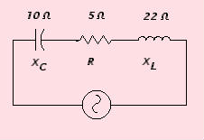
 In this circuit, we have a resistor, a capacitor, and a coil in series. Because the coil and the capacitor act in an opposite manner, they tend to cancel each other out. We say that the coil is additive, and the cap is subtractive in nature.
If the inductive reactance, and the capacitive reactance were equal in value, they would effectively cancel each other completely out, and only the resistance would be seen. In this special case, we would say that we have a resonant circuit
Just as we must solve problems with resistance in series… we must also be able to add the various reactances together, and come up with a common ground. Resistance is pure resistance. Capacitive reactance is a resistance that is subtractive in nature. Inductive reactance is additive in nature. Combining the three, we come up with a new term called IMPEDANCE, which is symbolized by the letter Z. Just like resistance, the formula is different for impedance in series and in parallel. The formula for impedance in series is:
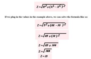
If we plug in the values in the example above, we can solve the formula like so:
Note that this method is not much different than what we did in lesson 25. There we added phase “vectorially”. This is a function of trigonometry, where in a given triangle, A2+B2=C2. (The square of the hypotenuse is equal to the sum of the square of the two sides).
The same applies here. We can say that the A2 is the resistance, the B2 is the combined capacitive and inductive reactances, and the C2 is the Impedance ( Z ).We could plot out our capacitance and inductance vectorally, but this would use up lots of time and paper. We can simply solve the same problem using this formula, where the B2 is equal to the sum of the reactances of the coil and the cap. We always subtract the capacitive reactance from the inductive reactance, because capacitors are subtractive.
Whenever a circuit has both inductors and capacitors, there is a given frequency at which XL is mathematically equal, but opposite to XC. In this case, XL is +3 and SC is – 3.
When this happens, the Total Resistance is equal to the pure resistance of the resistor, and the capacitor and inductor cancel each other out for all intents and purposes.
We call this that the circuit is in RESONANCE. When a circuit is resonant, it is at it’s lowest point in resistance. Any increase, or decrease in frequency will cause the circuit to have greater resistance.
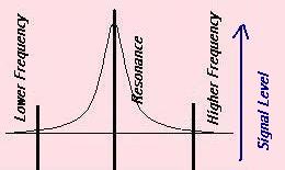 But because a circuit has less resistance at it resonant frequency, it will allow more of a signal to pass through at resonance than at a higher or lower frequency than the resonant frequency.
The frequency at which the circuit becomes resonant is (for our purposes) completely dependent on the inductance and capacitance of the circuit.
The “pure” resistance of the circuit does not affect the resonant frequency of the circuit.