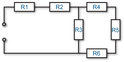
 Whenever we work with circuits in the real world, they are seldom as straightforward as a simple series or parallel circuit. Normally, they are a combination of the two, called a SERIES-PARALLEL circuit. While they look forbidding at first, you must keep in mind that ALL circuits can be broken down into smaller parts. They can be made simpler to work with. Such is the case with the Series-Parallel circuit.
If you look at the example on the right, it has 3 resistors and 1 battery. R1 and R2 are both 10 W in parallel.
If we do the math (reciprocating the reciprocals), we come up with a total of 5W for these two. We can say that: R1&2 = 5W.
We also have R3 in the circuit, which is 20W. Once we have combined the 2 parallel resistors, we have a simpler circuit…. 2 series resistors. R1&2 and R3. If we add the value of these two resistors, we come up with
RTotal=R1&2+R3.
So RTotal=5W+20W=25W.
 Then if we know the voltage, we can find the current through the entire circuit, and through each individual resistor. Go ahead and try plugging in a voltage (like 25V) and finding the currents. You’ll be surprised at how simple it is.
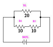
Let’s try another example. In the circuit on the right, we have 3 resistors again. But this time, they are configured differently. Do you see how you would combine them for the total resistance? First, you must add the 10 W resistors by adding them. This is simple because they are in Series.
10 W + 10 W = 20 W.
Using our parallel circuit formula then:
1
—————-
1 1
—– + ——
R1 R2
 We find that our total resistance for the circuit = 10W. Note that if we have the same battery (25V), our current turns out much different through the entire circuit.
So the same components, configured differently, will create a vast difference in the way the circuit works.
