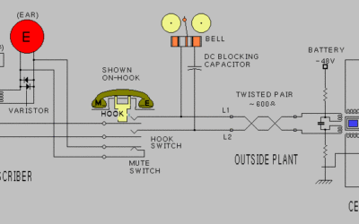
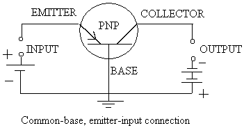
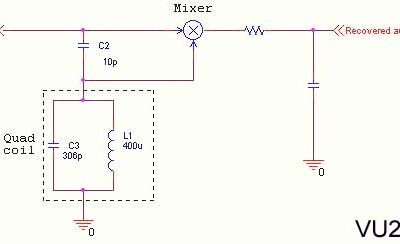
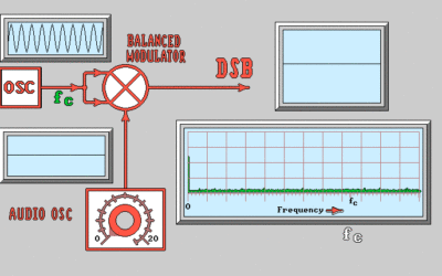
Sometime over the years, some bright soul determined that it would be difficult to draw a picture of every component that you decided to put into a circuit. However, they needed a way to tell their colleagues about discoveries and accomplishments. So a system was developed that was a sort of “electrical shorthand”. They call it a SCHEMATIC DIAGRAM and the individual component representations are called SCHEMATIC SYMBOLS. Throughout the course, I will be introducing you to the various SCHEMATIC SYMBOLS one by one. This lesson will take you through the first two symbols, and describe how they are used in a circuit. The first three SCHEMATIC SYMBOLS you will be introduced to are the lamp, battery and resistor.
 Remember that a resistor is any device which causes electrical friction. In electronics, the resistor can be substituted for any current load. The schematic symbol for a battery can likewise be substituted for any direct current supply voltage. So, in essence, we could theoretically use our battery and resistor to represent our light bulb circuit.
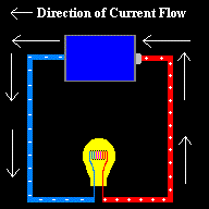
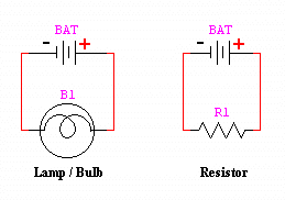 You will notice that the picture on the left is the same one we just looked at. The one on the right actually has two schematic diagrams. The schematic on the left is an exact representation of the picture on the left. The schematic on the right we say is an ELECTRICAL EQUIVILANT circuit for the one on the left. Any circuit, no matter how complex, can be broken down to being a source and a load. The resistor represents the light bulb, which is the load of the circuit. Anytime you are having a problem figuring out how a circuit works, it can be helpful to break it down to an ELECTRICAL EQUIVILANT circuit.The SCHEMATIC SYMBOL for the light bulb is pretty self explanatory. The Schematic for the resistor looks like a series of sharp turns. Just remember that on a road, you have to slow down at sharp turns, and electrical flow (current) has to slow down at a resistor. The battery needs a little explanation. The lines represent the electrodes of a battery. Note that the SHORT line is always the NEGATIVE terminal, and the longer line is always the POSITIVE terminal.

