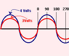
 Phase is the timing relationship between two different sine waves. If two generators are connected across a given load in series, and if their armatures begin rotating together at exactly the same time and speed, two different alternating voltages will be produced. In the example to the left, one is a 4 Volt sine wave, and the second is a 3 Volt sine wave.
If we examine the closely, we find that both sine waves meet up at the 0o and 180o points. Furthermore, they both peak out at 90o and 270o respectively. We say, then, that both of the two waves produced by the two different generators are IN PHASE with each other.
Whenever two waves are in phase, like these are, the voltage resulting from the two waves will not be the same as either of the two voltages. The resulting voltage will be the SUM of the two voltages. In this case, we have 3 and 4 volts being produced by the generators, and the resulting output voltage would be 3+4 or 7 Volts.
This is because the energy in the two voltages work together, and combine to add up to 7 Volts. But what happens if the generators are NOT in phase?
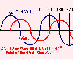 Whenever two waves are combined out of phase, the resultant waveform is not so simple to figure out. Look at the on the right. The 3 Volt generator was started later than the 4 Volt generator. We say that the 3 Volt wave LAGS behind the 4 volt wave. In this case, the 3 Volt wave LAGS by 90o.
Voltages that are out of phase can not be added simply by adding them together, as we do with in phase waves. We must resort to a sort of “high math” called VECTOR ADDITION. To make it simpler to understand, Vector math simply means that we break out a piece of graph paper, and plot the 3 volt wave horizontally (left and right), while we plot the 4 volt wave vertically (up and down).
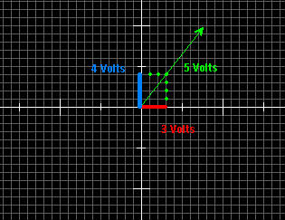 Examine the chart to the left to see how this works. Using our 3 and 4 volt waves, we draw the two lines on the graph paper. Then we draw a “mirror image” of the same two lines.
When we are finished drawing the mirror image, it should form a parallelogram. Now we draw a diagonal line from the “0” point in the middle of the graph, to it’s opposite corner of the parallogram. The distance from the 0 point to its opposite corner will be the vectoral sum of the two voltages.
This method works, no matter what the Phase difference is between the two voltages, but does require a little modification if it is different from 90o.
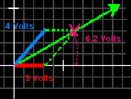 Let us assume now, that instead of the two waves being 90 degrees out of phase, that the 4 Volt wave is lagging the 3 volt wave by 45 o this time.
The method of finding their vectoral sum is basically the same. First we plot the 3 Volt wave horizontally on the chart. Next we measure 45o to draw the second line. We draw the 4 Volt line 45o from the 3 Volt wave.
Now again we draw a parallelogram, reflecting the origional two plotted voltages. We draw a line bisecting the parallelogram from the 0 point to its opposite corner. The length of the resultant line indicates the vectoral sum of the two original voltages.