 |
|
|
|
|
|||||||||
|
As we mentioned earlier, there were 2 types of circuits, SERIES and PARALLEL. We have already gone thru Series. Now we are going to discuss the difference between a Series and a PARALLEL circuit. In the series circuit, all the electricity followed the same path. In our waterflow representation, this meant that all the water flowed through 1 pipe. In PARALLEL circuit, however, there are multiple paths that current can flow through. |
 |
|||||||
|
Notice that in the picture to the left, that there are 3 different paths which the water can take. All 3 paths have the same incoming pressure, but the flow of some paths can be more restricted than in others. Parallel circuits in electronics work on the same principle. While there may be multiple paths for the electricity to flow through, the electrical pressure (Voltage) remains the same through all paths. |
|||||||
 |
|||||||
|
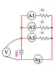
As you can see from the diagram on the right, there are 4 meters placed in this circuit to measure the current. |
|||||||
|
The first 3, (A1, A2, and A3) measure only the current flowing through that individual leg of the circuit. The 4th, AT measures the Total current of the circuit. If you take the three individual currents, and add them all together, they will equal the total current, measured on the 4th meter. From this we can see that the current in a parallel circuit is additive. I1 + I2 + IX... = ITotal |
|||||||
|
Resistance in a parallel circuit can be quite a bit trickier than in a series circuit. It is found by "Reciprocating the Sum of the Reciprocals". Simple. Taking the reciprocal of a number means dividing "1" by that number. The reciprocal of 2 would be 1 divided by 2 or ½. Most modern calculators have a [1/X] button just for this purpose. So if you take the reciprocals of the values of all of the resistors, which would, of course, give you a bunch of fractions, and add them all up, then reciprocate their sum, you would have the answer. The formula would look something like this: 1 ----------------------------------- 1 1 1 1 1 ---- + ---- + ---- + ---- + ---- + R1 R2 R3 R4 RX...
|
|
Let's begin with a very simple circuit: 2 resistors and 1 battery.
You are given the following information about the circuit: |
||