|
|
|
|
|
|
|
|
|
|
|
|
|
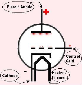
Now we apply a voltage to the Grid. If we apply a small Positive
voltage, electrons flow from the cathode toward the grid. Since the Grid
voltage is small, and the Plate voltage is large, the electrons continue
past the Gird on to the Plate. The Grid, being closer to the Cathode than
the Plate is, gets the electrons moving in the direction of the Plate, and
sort of helps them along their way. Because of this, more current flows to
the Plate with a Positive Grid than with an un-energized Grid or no Grid
at all. |
|
|
|
If, however, we apply a Negative voltage to the grid, it creates a
Negative field between the Cathode and the Plate. This field restricts the
flow of electrons moving to the plate. Sort of like pinching a garden
hose. The tighter we pinch it, the less water flow there is. The same is
with the Control Grid of an electron tube. The more Negative we swing the
grid, the less current flows at the plate. |
|
|
|
So we find, then, that when the Grid Voltage swings Positive,
Current flow is increased at the Plate, and when the Grid Voltage swings
Negative, the Current flow is decreased at the Plate. Speaking
"mathematically", we would say that the "Grid Voltage is directly
proportional to the Plate Current ". In plain english, we can say that we
can control the CURRENT of the PLATE, by changing the VOLTAGE of the
GRID. |
|
|
|
So then, what happens when we apply an ALTERNATING current to the
grid? |
|
|
|
If we place an AC signal on the Control Grid of a triode, the signal
swings from Positive, to Negative, then back to Positive. As it does so,
the Plate Current swings directly with the Grid Voltage. If we have a
fixed resistance load ( a resistor ) across the output of the Plate, we
will notice that when the Plate Current goes High, the Plate Voltage goes
Low. As the Plate Current goes Low, the Plate Voltage goes High. ( Ohms
Law applies ... E=IR ). |
|
|
|
So if we compare, when the GRID Voltage swings High.... the PLATE
Voltage swings Low. The Voltage at the Plate swings OPPOSITE the voltage
of the Grid. The Output of the Plate will look like a mirror image of the
Input to the Grid. |
|
|