Home Sanskrit Sloka
Website by VU2FD
 
BACK TO RADIO CLASSES

Knowing what a diode is, or how a triode works is of little use unless you have some practical knowledge of how it can be applied within a circuit. We are going to begin with a VERY basic schematic of an early transmitter.

Picture

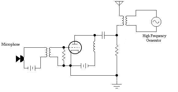
When ever we are looking at a schematic diagram, we must look at it from 2 directions. Top to Bottom, and Left to Right:

First: No circuit can operate without some kind of Power, In this schematic, we have 2 batteries shown operating the circuit.

    While it may be true that electrons flow from negative to positive, it is usually easier to understand movement of power through a circuit using the Conventional current flow theory, otherwise known as the Franklin theory, which states that electricity flows from positive to negative. When looking at a schematic, it is customary to start with the highest positive voltage, which is normally at the top of the diagram, and work your way down to the lowest voltage, usually ground, which is located at the bottom of the diagram.

Second: The purpose of most circuits is to move some kind of signal. Signal flow normally goes from Left to Right.

    Signals can be anything from basic AC sine waves, to audio, video, radio, or data signals. They normall begin with some signal source on the left, and move to the right.

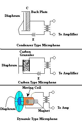
Before you can fully understand the circuit, I will have to give you a brief introduction to microphone construction and theory. In the following illustration, I show a breakdown of how 3 different types of microphones work. In all three types, when we speak into the microphone, the sound waves from your voice create vibrations in the air. When these sound waves reach the microphone, they vibrate the diaphram of the microphone, which is usually a very thin layer of flexible plastic. This diaphram works like the eardrum in your ear, and vibrates back and forth at the same frequency ( pitch ) and amplitude ( volume level ) of the sound waves that stimulate it. The diaphram in all three types move left and right as shown. The third pictures a 3 dimensional representation of a magnetic type microphone for ease of understanding

In the case of the Condenser type, a condenser is basically a capacitor. Here we have 2 electrodes, separated by an air dialectric. When the diaphram moves, it moves one of the plates, which changes the distance between the plates. Since the distance between the plates governs the capacitance of a capacitor, by moving one plate, we change the capacitance of the capacitor. The changes in capacitance are directly proportional to the frequency and amplitude of the sound waves picked up by the diaphram. So the electrical signal coming out of the microphone reflects the sound waves picked up by the diaphram.

Carbon microphones work in similar fashion to Condensor microphones, except that instead of an air dialectric, we have carbon, which when compressed, changes its resistance instead of its capacitance. In short, we have a variable resistor, which changes reflect the incoming sound.

Picture

Finally, a dynamic, or magnetic microphone has a moving coil, which is moved by the diaphram when it vibrates. The hair like strands of wire in the coil move back and forth with the incoming sound, cutting the magnetic field of the permanent magnet. As you recall, when a wire cuts the field of a magnet, an electrical current is induced in the wire. When the coil moves, it generates a small electric current, which changes with the incoming sound.

Many microphones, such as the Carbon and Condenser type require power, whether via battery or "phantom power" to operate. Because a Dynamic microphone actually generates an AC current, it needs no outside power source.

The positive side of the battery is connected to the microphone directly. The negative side passes DC current through the coil to the other side of the microphone. Think of the microphone as a very thin membraned capacitor, with air acting as a dilectric. As we speak into the microphone, the vibration of the sound waves from our voice generates an alternating current, which varies directly in amplitude ( volume level )and frequency ( pitch ) with the changes of our voice. This alternating current is applied to the coil, causing it to set up an induced electromagnetic field, which rises and colapses, changing along with our speach.

Picture
Picture

The Tube Amplifier!

First let's go over power, then signal. The tube, being the active device in this circuit, is powered by the battery. The Positive side of the battery produces a positive voltage, which passes through the plate coil to the PLATE of the Tube. The Plate, having a positive potential, is ready to begin attracting electrons. We'll say we have a BIG battery, and it puts out 200 Volts.